News & Press Release
Weathernews' Meteorological and Oceanographic Satellite WNISAT-1R the First Japanese Satellite to Succeed in a GNSS-R Mission
Weathernews Inc. (Chiba, Japan; CEO: Chihito Kusabiraki) announced that its microsatellite, WNISAT-1R, developed in collaboration with Axelspace Corporation (Tokyo, Japan; CEO: Yuya Nakamura) has succeeded in its GNSS-R (Global Navigation Satellite System - Reflectometry) mission. This is the first success by a Japanese space mission and the third globally, following UK-DMC/TDS-1 of Surrey (UK) and CYGNSS of NASA (USA). Using GPS signals reflected off the earth’s surface brings the potential to monitor earth surface conditions, even at night or on a cloudy day. GNSS-R may become a new observation system in combination with optical cameras. Weathernews will attempt to monitor ocean waves and surface winds using GNSS-R observation.
Successful Reception of Reflected GPS Signals
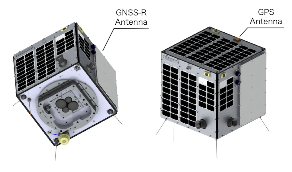
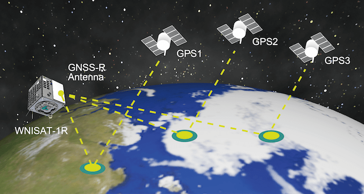
GNSS-R mission equipment for the experiment of GNSS reflectometry is installed on WNISAT-1R. GNSS-R missions are aimed to research the possibility of monitoring the earth’s surface condition using reflected GPS signals (Fig. 1). GNSS-R does not need to transmit a signal as an observational probe. This is one of the great benefits of microsatellites, i.e. there is no need to have a large electric power source. In addition, GNSS-R observations can be conducted even at night or on a cloudy day. Over 30 GPS satellites will provide WNISAT-1R with the opportunity of simultaneous multi area observations. WNISAT-1R, which was launched by Weathernews in July 2017, has succeeded in receiving GNSS-R signals and created a Delay Doppler Map (DDM).
Received signal analysis
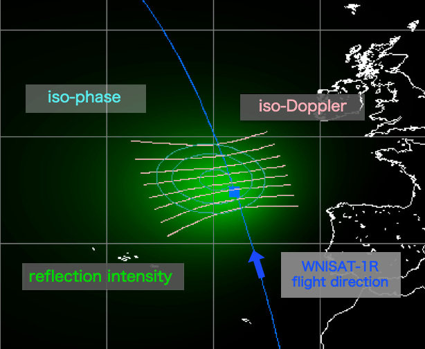
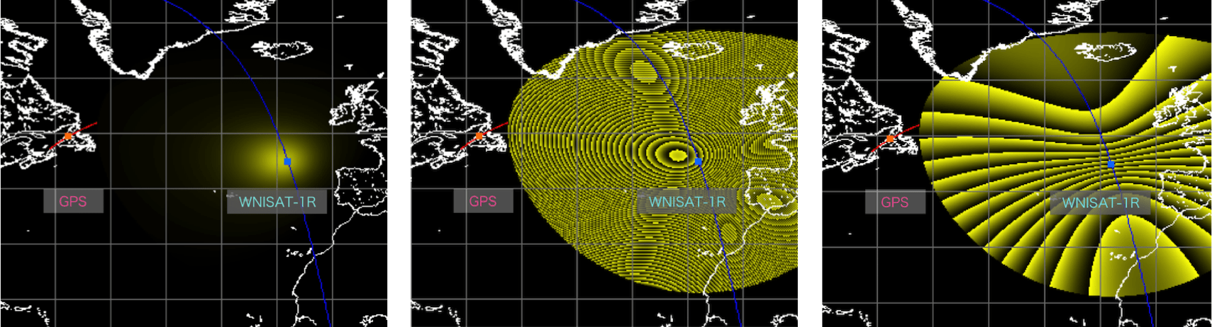
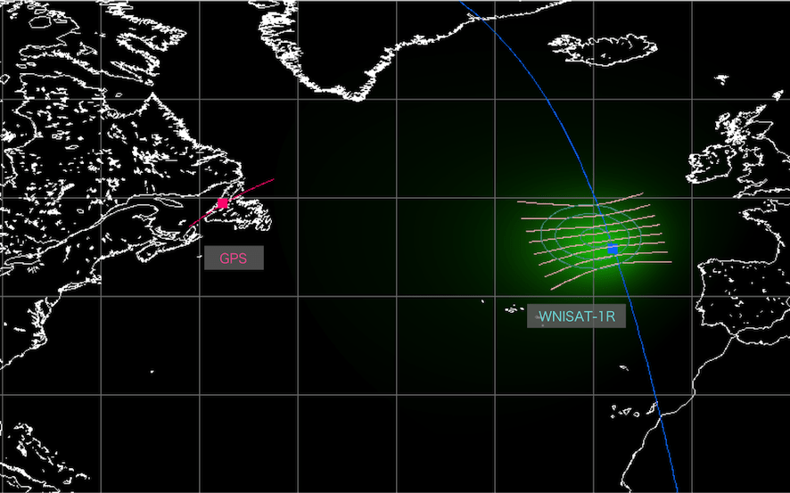
Signals from GNSS satellites travel into deep space after being reflected off the earth’s surface. This reflected signal contains data through which we can know the characteristics of the earth’s surface. The reflected signals received by WNISAT-1R are reflected off wide area of the earth’s surface. This area depends on the earth surface conditions, i.e. rough surface like seas with waves, specular surface like a calm sea, vegetated land, deserts, etc. A rough surface provides defuse reflection and a smooth surface provides specular reflection. In the case of specular reflection, the distance traveled by the received signal is minimum. A mixed status of delayed signals shows the surface conditions. The longer the delay means the more roughness of the surface. The same discussion can be had regarding the Doppler shift. Doppler shift depends on the velocity component of the direction in which the satellite is moving. A rough surface causes a variety of paths traveled by the signal. Therefore, a rough surface provides a wider Doppler shift. DDM (Delay Doppler Map) is suitable for this kind of analysis. DDM is a chart that plots the correlation of the phase and Doppler system. Thus, a DDM indirectly shows the earth surface condition. Of course, the location of the reflected point should also be considered, i.e. whether it is close to, or far away from WNISAT-1R. This causes differences in the characteristics. In the case of the sea surface, wind causes surface roughness. It suggests a relation between wind and roughness. Fig. 2 shows examples of actual DDMs observed by WNISAT-1R at different positions on August 17th, 2017. The position of WNISAT-1R and GPS points, reflection intensity, iso-phase and iso-Doppler are shown in Fig.3.
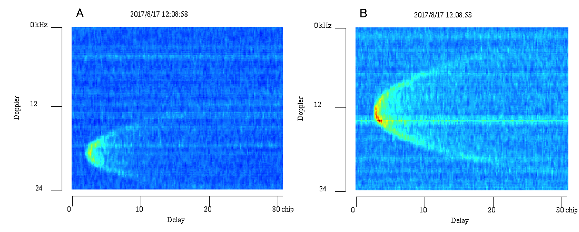
The vertical axis shows the Doppler shift frequency and the horizontal axis shows the delay.
WNI expects that further experimental observations will help clarify the the potential of wind and oceanic wave estimation through this methodology.
◇ Reference Information